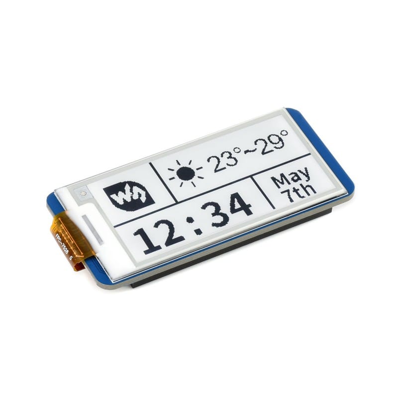
I wanted to use the Waveshare ESP32-S3-PICO with the 2.13” Black/White E-Ink E-Paper Display Module for Raspberry Pi Pico (250×122) board, as both are the same form factor.
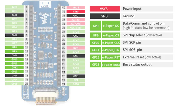
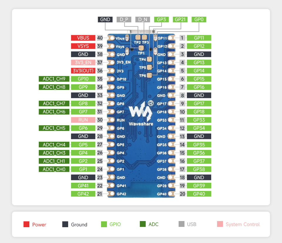
I realised that the pinout would be different, but checking both the ESP32 Pico and the PI Pico, the power pins all match up and the pins used by the e-paper board all looked perfectly usable on the ESP32.
https://www.waveshare.com/wiki/Pico-ePaper-2.13 https://www.raspberrypi.com/documentation/microcontrollers/pico-series.html https://www.waveshare.com/wiki/ESP32-S3-Pico
I grabbed an existing e-paper display I had, which is the Waveshare 400x300, 4.2inch E-Ink display module, three-color (there are a few variations on this model, I believe mine is the b variant) and started hooking things up.
Working on this for a while, I struggled to get the output working, despite successfully using the display in the past, what I didn’t fully appreciate was that the GxEPD2 library expects you to use the hardware SPI interface on the microcontroller. This is pins 11&12 on the ESP-32-PICO, once I’d connected this up the board was working fine.
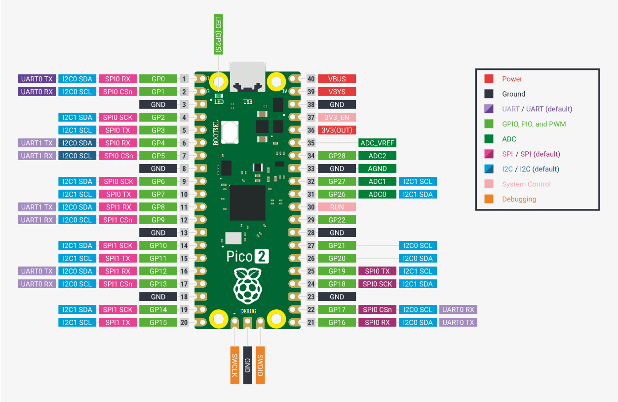
Comparing the pinout images of the ESP32 Pico and the PI Pico, the PI uses pins 35&36. This meant even if I used the same position GPIO ports, the pinout of the SPI would differ.
After some digging around and assistance from ChatGPT, I found that you can initialise the SPI before initialising the display, and give additional parameters to the initialisation method to get it to use the custom SPI pins.
#include <GxEPD2_3C.h>
#include <Fonts/FreeMonoBold9pt7b.h>

static const uint8_t EPD_BUSY = 38; // to EPD BUSY
static const uint8_t EPD_RST = 37;  // to EPD RST
static const uint8_t EPD_DC = 33;   // to EPD DC
static const uint8_t EPD_CS = 34;   // to EPD CS
static const uint8_t EPD_SCK = 35;  // to EPD CLK
static const uint8_t EPD_MOSI = 36; // to EPD DIN
static const uint8_t EPD_MISO = -1; // Master-In Slave-Out not used, as no data from display

GxEPD2_3C<GxEPD2_420c, GxEPD2_420c::HEIGHT> display(GxEPD2_420c(/*CS=D8*/ EPD_CS, /*DC=D3*/ EPD_DC, /*RST=D4*/ EPD_RST, /*BUSY=D2*/ EPD_BUSY));


void setup()
{
  Serial.begin(115200);
  while (!Serial)
    delay(10); // Wait for serial connection
  Serial.println("Starting setup...");

  SPI.begin(EPD_SCK, EPD_MISO, EPD_MOSI, EPD_CS);
  display.init(115200);
  helloWorld();
  display.hibernate();
}
With this the display works fine. Once the 2.13” display arrives and it working I’ll add some more notes !